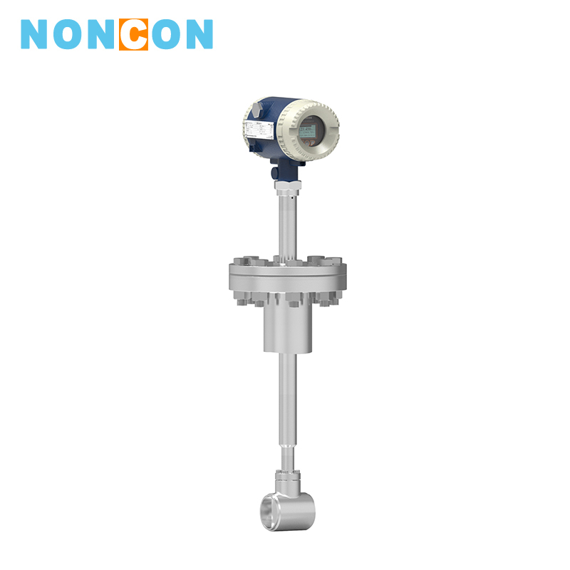
LUGC Insert Type Vortex Flowmeter
application:
medium:
■Simple structure can be made into online installation type
■Suitable for measurement of large diameter gas and steam flow etc.
■Convenient installation free of tube design
■Suitable for measurement of large diameter gas and steam flow etc.
■Convenient installation free of tube design
Detailed introduction
Ⅰ.Flow range of insert type vortex flowmeter
Ⅱ.Product selection
| Model | Interpretation | ||||||
| LUGC | ¨ | ¨ | ¨ | ¨ | ¨ | ¨ | Insert type vortex flowmeter |
| Connection mode | 1 | Flange connection(for full tube vortex flowmeter) | |||||
| 2 | Flange clamping(for full tube vortex flowmeter) | ||||||
| Measured medium | 1 | Liquid | |||||
| 2 | General gas | ||||||
| 3 | Compressed air | ||||||
| 4 | Steam | ||||||
| inside nominal diameter | 250 | 250mm | |||||
| 300 | 300mm | ||||||
| 400 | 400mm | ||||||
| 500 | 500mm | ||||||
| 600 | 600mm | ||||||
| 700 | 700mm | ||||||
| 800 | 800mm | ||||||
| 900 | 900mm | ||||||
| 1000 | 1000mm | ||||||
| 1100 | 1100mm | ||||||
| 1200 | 1200mm | ||||||
| 1300 | 1300mm | ||||||
| 1400 | 1400mm | ||||||
| 1500 | 1500mm | ||||||
| Compensation | N | Uncompensated(suitable for volume flow measurement occasions) | |||||
| T | Temperature compensation(suitable for saturated steam) | ||||||
| P | Pressure compensation(suitable for saturated steam) | ||||||
| F | Temperature and pressure compensation((suitable for superheated steam and compressed air) | ||||||
| Output type | N | Sensor type:24VDC power supply, output three-wire pulse signal | |||||
| A | Transmitter type:24VDC power supply,Output current signal 4~20mA | ||||||
| B | Intelligent:Lithium battery power supply,status display(Dual power supply, pulse output optional) | ||||||
| C1 | Intelligent:24VDC power supply,status display、output 4-20mA(pulse output optional) | ||||||
| C2 | Intelligent:24VDC power supply,status display、output two-wire system 4-20mA HART communication、(pulse output optional) | ||||||
| C3 | Intelligent:24VDC power supply,status display、RS485 communication、(Dual power supply, pulse output optional) | ||||||
| accuracy class | 2 | 2.0 level | |||||
| 3 | 3.0 level | ||||||
| material quality | S | 304 stainless steel | |||||
| L | 316(L)stainless steel(Customized,long supply cycle) | ||||||
| Explosion-proof | N | Non-explosion-proof type | |||||
| E | Explosion-proof type,ExdIICT6 | ||||||
| Pressure grade | P | Actual pressure grade(customization for high pressure, long supply cycle) | |||||
1. Structure style
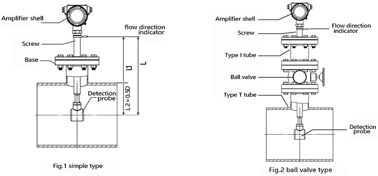
2. Simple flowmeter installation
■Open a φ100 circumferential notch at the mounting point that meets the requirements for the straight pipe section of the flowmeter.
■Use the lower pipe section of the φ109x4.5mm pedestal to weld to the circumferential notch, and no obvious skew after finish.
■Insert the speed probe into the pipe and adjust the insertion depth so that the center of the probe matches the center axis of the pipe. The angle between the center line of the probe and the center axis of the pipe should not exceed 5 degrees, and then adjust the flow direction indicator to be the same direction as the flow of the fluid.
■Dock the flange or ball valve with the welded base and fasten it with bolts.
 Chinese
 English
 Current position:



 South China