 Chinese
 English
 Current position:
<
>
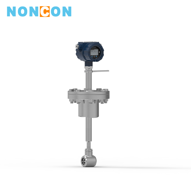
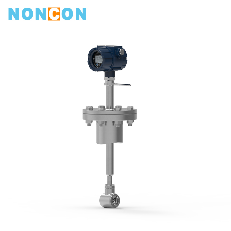
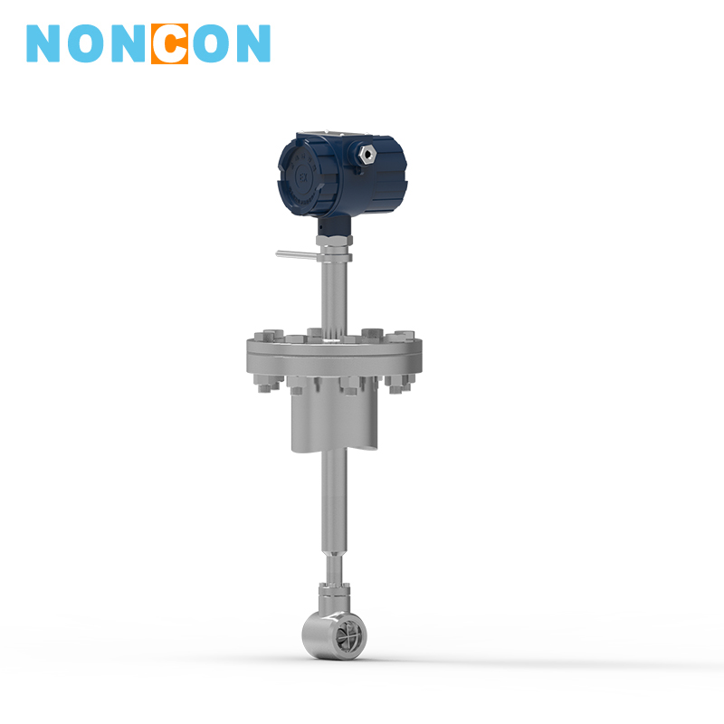
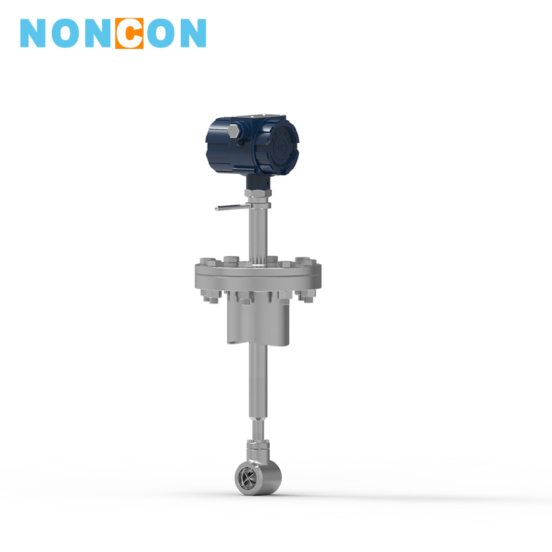
LWGC Plug-in Type Liquid Turbine Flowmeter
application:
medium:
LWGC (tangential) and LWCB (axial) plug-in type turbine flow sensors are matched with display meters to form a plug-in type turbine flow meter which can be widely used for measurement of large caliber pipeline source water circulating water clean water and other liquid flows andtotal amount.
Detailed introduction
Ⅰ. FeaturesCharacteristics of LWGC plug-in type turbine flowmeter
(1) The anti-impurity ability is strong, the tangential impeller in the fluid can release the suspended matter can be released when the tangential impeller is rotating at any time, so that it does not wrap around the blades of the tangential impeller.
(2) With strong anti-electromagnetic interference and anti-vibration ability.
(3) The structure and principle of the sensor and display meter are very simple and intuitive, and the user is particularly easy to master the use and maintenance technology.
(4) After replacing the impeller and bearing, the meter factor remains unchanged
(5) The flow range is wide with low downline flow rate.
(6) The measurement error of the total flow of the flowmeter is small
(7) It has almost no pressure loss, saving power consumption
(8) The sensor can be installed in the open air, and the whole sensor can be used in the water for a long time.
(9) When disconnecting sensors with shut-off valves ,it is not need to shut off the flow during installation and disassembly.
(10) Horizontal, vertical, inclined pipes can be used
(11) The purchase, installation and maintenance costs of the complete flowmeter are low.
Ⅱ.Meter Selection
| Mode | Description | |
| LWGC ¨ ¨ ¨ | ||
| Plug-in type | A1 | Simplicity |
| A2 | Online installation | |
| Impeller type | Q | Tangential type |
| B | Axial-flow type | |
| Nominal diameter | (mm) | User pipe nominal caliber |
| Output type | EN | Sensor type: 24VDC power supply, output three-wire pulse signal |
| EA | Transmitter type: 24VDC power supply, output two-wire 4 ~ 20mA | |
| B | Intelligent type: lithium battery power supply (dual power supply, pulse output can be optional) | |
| C1 | Intelligent type: 24VDC power supply, display and output two-wire 4~20mA (pulse output can be optional)) | |
| C2 | Intelligent type: 24VDC power supply, display and output 4-20mA HART communication (pulse output can be optional) | |
| C3 | Intelligent type: 24VDC power supply, on-site display, RS485 communication, (dual power supply, pulse output can be optional) | |
(1)Plug-in depth h
When the measured inner diameter of the measured pipe is DN ≤ 1000mm, plug-in depth
LWGC h =0.5DN- 20mm
LWGC h =0,5DN
Accuracy: ±5%, ±2.5%
Nominal pressure PN: 1.0Mpa
Temperature of the measured liquid: -20 ℃ ~ 120 ℃
Ambient temperature: -20 ℃ ~ 70 ℃
(2) Distance from sensor to display meter: If the length of signal cable is increased, it can reach more than 1000m. The required cable length should be presented in the order contract or agreement
(3) Requirements for the length of straight pipe: The length of the upstream straight pipe of the sensor should be no less than 20DN, and the length of the downstream straight pipe should not be less than 7DN to ensure accuracy. If the length of the straight pipe cannot meet this requirement, after the calibration of the meter factor KDN is carried out on-site, which will be used.
(4)Measurement range
| Model | The measured inner diameter of the pipe to be tested mm | Plug-in rod length mm | Flow range corresponding to the nominal diameter DN m³/h | ||
| Full flow range | Flow range of accuracy is ±2.5% of the displayed value | Flow range of accuracy is ±5% of the displayed value | |||
| LWGC-100 | 100 | 6-150 | 10-150 | <10-6 | |
| LWGC-150 | 150 | 13-200 | 20-200 | <20-13 | |
| LWGC-200 | 200 | 23-300 | 40-300 | <40-23 | |
| LWGC≤400 |
100 150 200 250 300 350 400 |
906 |
6-150 13-200 23-300 36-450 52-650 70-900 92-1100 |
10-150 20-200 40-300 62-450 90-650 120-900 160-1100 |
<10-6 <20-13 <40-23 <62-36 <90-52 <120-70 <160-92 |
| LWGC≤800 |
500 600 700 800 |
1106 |
150-1800 220-2500 280-3500 380-4500 |
250-1800 360-2500 450-3500 640-4500 |
<250-150 <360-220 <450-280 <640-380 |
| LWGC>800 |
900 1000 1100 |
1306 |
460-5800 600-7000 700-8500 |
800-5800 990-7000 1200-8500 |
<800-460 <990-600 <1200-700 |
1. technical requirements
Unmarked dimension and materials are determined by the user according to the compressive strength and anti-corrosion requirements. The position of the mounting base seat on the pipe should be straightforward and intuitively there should be no significant deflection.
Non-steel pipes can be clamped to the “mounting base seat” by clamps, but the clamp must have a clearance dimension of 85 mm as shown in Figure (1) so that bolt M16×65 can be plugged in through the gap when installing the ball valve.
Flange connection dimension standard: GB42164-8414
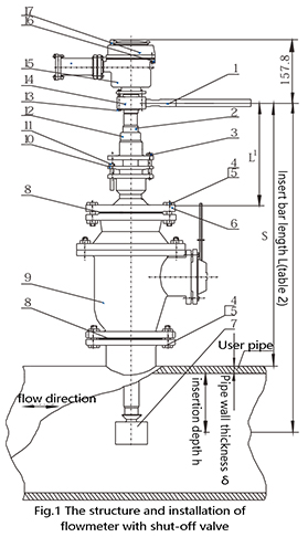
1. positioning rod
2. the pluging rod
3. locking bolt M8×6016
4. bolt M16 × 65
5. nut M16
6.base seat
7.turbine head
8.sealing gasket
9.ball valve
10.packing gland
11. packing compression bolt M8 × 45-Q12
12.ocking sleeve
13. bolt M6 × 45
14.sleeve
15.outer shell
16.bolt M16×16
17.cover
2. Product structure is as follows:


 South China