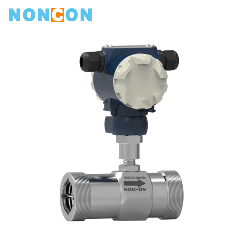
LWGY Liquid Turbine Flowmeter
application:Water diesel methanol etc. without impurities no corrosive liquid.
medium:
High precision high quality high performance
LWGY series turbine flowmeter is a new generation of turbine flowmeters which has absorbed the advanced technology of flow meter at home and abroadand is manufactured according to JB/9246-199 standard. It has the characteristics of simple structure light weight high precision good reproducibility high responsiveness easy installation and maintenance.
It is widely used to measure the liquid in closed pipeline. The liquid does not corrode stainless steel 1cr18Ni9Ti 2Cr13 and corundum AI203 cemented carbide and has no impurities such as fiber particles. The kinematic viscosity at working temperature is less than 5×10⁻⁶m2/s.For liquids with a kinematic viscosity greater than 5 × 10 m / s the flow meter can be used after real liquid calibration.If it is matched with a display instrument with special functions it can also perform quantitative control excess alarm etc which is an ideal meter for flow metering and energy saving.
1. High-definition LCD display
2. Three-key parameter setting and debugging
3.5-segment polyline correction function for non-linear signals
4. Linear current output
5. Frequency pulse output: DC power can be used to supply power to the pulse output circuit. At this time the meter can convert the mV pulse signal output by the turbine sensor into a standard TTL pulsewhich can be used for linear signal users debugging.
Detailed introduction
Ⅰ.Product Characteristics■High precision, generally up to ±1%R, ±0.5%R, and high precision type can be up to ±0.2%R;
■Good repeatability with short-term repeatability of 0.05%-0.2%. Due to good repeatability, such as frequent calibration or online calibration, it can get very high precision,which is the preferred flow meter in trade settlement;
■Output pulse frequency signal, it is suitable for total metering and connected with computer, without zero drift, and with strong anti-interference ability;
■It can obtainHigh frequency signal (3~4kHz) with strong signal resolution;
■The range of medium and large caliber can reach 1:20, and the range of small caliber is 1:10;
■It has the characteristics of compact structure, light weight, convenient installation and maintenance, and large circulation capacity;
■It is suitable for high-pressure measurement, no need to open holes on the meter body, easy to make high-pressure type instrument;
■It has many special sensor types, which can be designed into various types of special sensors according to the special needs of users, such as low temperature type, two-way type, downhole type, sand mixing type, etc.
■It can be made into plug-in type, suitable for large caliber measurement, with low pressure loss, low price, continuous flow, and easy installation and maintenance.
Ⅱ.Structural Characteristics and Working Principles
(1) Structural Characteristics
The sensor is a hard alloy bearing thrust type, which can ensure accuracy, improve wear resistance, and has the characteristics of simple structure, firmness and convenient assembly and disassembly.
(2)Working principle
When the fluid flows through the sensor housing, since the blade of the impeller has a certain angle with the flow direction, the force of the fluid causes the blade to have a rotational moment. After the friction torque and the fluid resistance are overcome, the blade rotates. After balancing the torque, the rotational speed is stable. Under certain conditions, the speed is proportional to the flow rate.Due to the magnetic permeability of the blade, it is in the magnetic field of the signal detector (composed of permanent magnet and coil). The rotating blade cuts the magnetic line and periodically changes the magnetic flux of the coil, so that the electric pulse signal is induced at both ends of the coil. This signal is amplified and shaped by the amplifier to form a continuous rectangular pulse wave with a certain degree of amplitude, which can be transmitted to the display instrument, showing the instantaneous flow or total amount. Within a certain flow range, the pulse frequency f is proportional to the instantaneous flow rate Q of the fluid flowing through the sensor. The flow equation is: Q=f/k*3600
f—pulse frequency [Hz]
k—the meter factor of the sensor [1/m3], given by the checklist
The meter factor of each sensor is filled in the verification certificate by the manufacturer, and the k value is set in the matching display meter to display the instantaneous flow rate and the cumulative total amount.

Ⅲ.Meter classification
1.According to the meter function, LWGY series turbine flowmeter can be divided into 2 categories, namely: (1) turbine flow sensor / transmitter (2) intelligent display turbine flowmeter
(1) Turbine flow sensor / transmitter
This type of turbine flow product itself does not have function of on-site display, only transmitte the flow signal far. The flow signal can be divided into pulse signal or current signal (4-20mA). The meter price is low, with high integration, and small volume,which is especially suitable for use with computer control systems such as secondary display, PLC and DCS.
According to different output signals, these products can be divided into LWGY-□ N-type and LWGY-□ A-type.
LWGY- N-type sensor: 24VDC power supply, three-wire pulse output, high level ≥8V, low level ≤0.8V; signal transmission distance is ≤1000 meters;
LWGY-□A type transmitter: 24VDC power supply, 2-wire 4-20mA output, signal transmission distance ≤1000
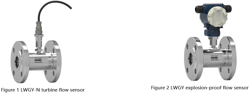
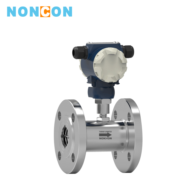
This type of turbine flow products are divided into basic type and explosion-proof type (Exdiict 6), and the shape is as shown in Figure 1 (Figure 2).
(2)Intelligent display turbine flowmeter
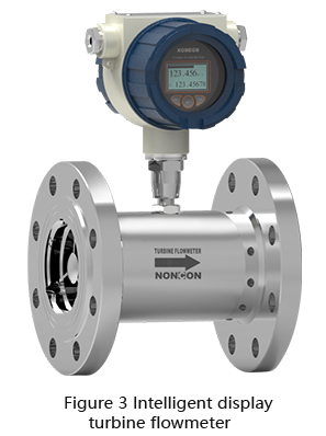
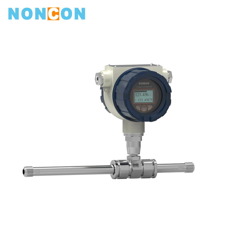
The double-row liquid crystal on-site displayc is used for the new intelligent meter integrating turbine flow sensor and display calculation using advanced ultra-low-power single-chip microcomputer technology adopts, which has the advantages of compact mechanism, intuitive and clear reading, high reliability, no external power interference, lightning strike resistance and low cost.The meter has three-point correction of the meter factor, intelligently compensates the nonlinear meter factor, and can be corrected on site. The high-definition liquid crystal display simultaneously displays instantaneous flow and cumulative flow, with clear function. All valid data is not lost after 10 years of power failure. This type of turbine flowmeter is explosion-proof.
The explosion-proof grade is: EXDIICT 6.
This type of turbine flowmeter can be divided into LWGY-□B type and LWGY-□C type according to the power supply mode and whether it has remote signal output.
LWGY-□B type: 36V/10Ah lithium battery is uesd for the power supply (can run continuously for more than 3 years);
LWGY-□C type: 2AVDC external power supply is used for the power supply, and outputs 4-20mA standard two-wire current signal, and HART communication or RS485 communication function can be increased according to different site needs.
Ⅳ.Product Classification Description
1.According to different installation methods

2.Outline drawing of flange installation

Ⅴ.Selection Instructions
| Model | Description | |
| LWGY- ¨ ¨ ¨ ¨ ¨ ¨ ¨ | ||
| Nominal diameter | 4 | 4mm |
| 6 | 6mm | |
| 10 | 10mm | |
| 15 | 15mm | |
| 20 | 20mm | |
| 25 | 25mm | |
| 32 | 32mm | |
| 40 | 40mm | |
| 50 | 50mm | |
| 65 | 65mm | |
| 80 | 80mm | |
| 100 | 100mm | |
| 125 | 125mm | |
| 150 | 150mm | |
| 200 | 200mm | |
| Connection method | L | Thread(DN4mm - DN50mm) |
| F | Flange type(DN15mm- DN200mm ) | |
| Signal detector type | P |
Normal aviation connector with 4 m cable (for N-type output type) |
| H |
Hessmann connector (for N and A type output signal types) |
|
| E | Explosion-proof housing type (for N and A type output types) | |
| D | Display type housing (for B, Cl, C2, C3 output types) | |
| Output type | N | Sensor type: 24VDC power supply, output three-wire pulse signal |
| A | Transmitter type: 24VDC power supply, output 4 ~ 20mA current signal | |
| B | Intelligent: lithium battery power supply, on-site display (dual power supply, pulse output can be optional) | |
| Cl | Intelligent type: 24VDC power supply, on-site display, output 4 ~ 20mA (pulse output can be optional) | |
| C2 |
Intelligent type: 24VDC power supply, on-site display, output two-wire 4 ~ 20mA HART communication, (pulse output can be optional) |
|
| C3 | Intelligent type : 24VDC power supply, on-site display, RS485 communication, (dual power supply, pulse output can be optional) | |
| Accuracy grade | 05 | 0.5 grade |
| 10 | 1.0 grade | |
| 02 | 0.2 grade (need to negotiate orders, production cycle is longer) | |
| Turbine type | W | Extended measurement range |
| S | Standard measurement range | |
| Material | S | 304 stainless steel |
| L | 316 (L) stainless steel (need to be customized, long production cycle) | |
| Explosion proof | N | Non-explosion proof type |
| E |
Explosion-proof tyoe,EXDIICT 6 |
|
| Pressure grade | P | Normal (refer to Table 3) |
Ⅵ.Installation Dimensions
Thread connection and flange connection are used for the installation of the sensor according to different specifications. The installation method is shown in Figure 4, Figure 5 and Figure 6. The installation dimensions are shown in Table 2.

| Nominal diameter(mm) | Nominal diameter(mm) | G | D(mm) | d(mm) | Number of holes n-d |
| 4 | 225 | G1/2 | |||
| 6 | 225 | G1/2 | |||
| 10 | 345 | G1/2 | |||
| 15 | 75 | G1 | Ф65 | Ф14 | 4 |
| 20 | 80 | G1 | Ф75 | Ф14 | 4 |
| 25 | 100 | G5/4 | Ф85 | Ф14 | 4 |
| 32 | 140 | G2 | Ф100 | Ф14 | 4 |
| 40 | 140 | G2 | Ф110 | Ф18 | 4 |
| 50 | 150 | Ф125 | Ф18 | 4 | |
| 65 | 170 | Ф145 | Ф18 | 4 | |
| 80 | 200 | Ф160 | Ф18 | 8 | |
| 100 | 220 | Ф180 | Ф18 | 8 | |
| 125 | 250 | Ф210 | Ф25 | 8 | |
| 150 | 300 | Ф250 | Ф25 | 8 | |
| 200 | 360 | Ф295 | Ф23 | 12 |
 Chinese
 English
 Current position:





 South China