 Chinese
 English
 Current position:


<
>
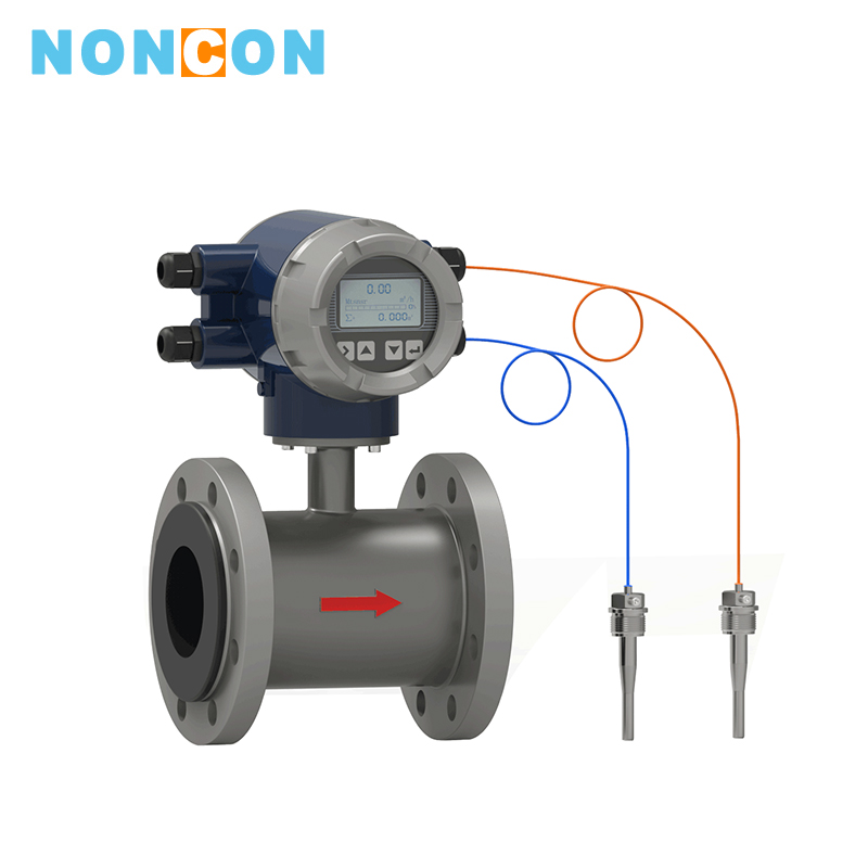
LDR Electromagnetic Heat Meter
application:Dyes, slurries, chilled water, hot water, acids, alkalis, etc., which are also highly corrosive or contain conductive liquids.
medium:
Dyes, slurries, chilled water, hot water, acids, alkalis, etc., which are also highly corrosive or contain conductive liquids.
LDR electromagnetic heat meter is designed for the special application of intelligent building distributed energy and heat exchange station, which can directly measure flow and cold and heat. It does not need additional flow totalizer and Pt1000. It is easy to install with low cost. The electromagnetic flow sensor is used as an electromagnetic heat meter for detecting the flow rate of the heat transfer fluid, and has the features of high precision, wide application range, and convenient and simple online calibration.
Detailed introduction
Ⅰ.Features■Measurement of cold and heat: the converter has the function of measuring cold and heat directly, and equiped with 2 standard Pt1000. It does not need to be equipped with a cold and heat flow totalizer to facilitate installation and reduce the cost of purchasing and installation.
■High reliability: After rigorous tests such as EMC, safety, high and low temperature, which are higher than national standards GB/T17616, G B/2423, GB/T16499.
■Fast response: Use 32BitMCU, 24BitADC and optimized filtering algorithm, fast response, accurate and stable measurement data, suitable for measurement and control when equipment is matched.
■Grounding electrode: NONCON patented technology, which forms measurement balance in measuring section and eliminates measurement error caused by poor grounding to ensure long-term measurement accuracy. It does not need to be equipped with a grounding ring to reduce material and installation costs.
■Separate IP68 technology: use specially detailed IP68 design technology, use special imported IP68 sealant, special IP68 cable and multiple IP68 seal design to prevent the condensation of the separate IP68 sensor.
■High signal-to-noise ratio: the sensor uses high signal-to-noise ratio technology. The converter uses low-noise and high-precision parts and design technology to facilitate measurement of minimum flow.
■Low-power design; optimized excitation circuit design, power consumption is reduced by more than 3 times compared with conventional electromagnetic flowmeters, and it can achieve energy saving in a large number of applications.
■Chinese display: use Chinese display LCD screen for easy understanding and operation
■Optimized power supply technology: use optimized power supply design, mature and reliable technology, high conversion efficiency, and reliable long-term use.
■Quick wiring:use the international best brand terminal block, which is fast, convenient and reliable, to ensure stable and reliable long-term measurement.
■Output signal: epuiped with standard RS-485, (4-20) mA, frequency / pulse, fast output response, and the port is provided with protection measures such as lightning protection.
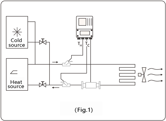
Ⅱ.Working Principle
Hot water (cold water) supplied by a heat source flows into a heat exchange system (radiator, heat exchanger or a complex system composed of them) at a higher (lower) temperature, and it flows out at a lower (higher) temperature.During this process, heat is released or absorbed to the user through heat exchange (Note: this process includes energy exchange process of the heating system and the cooling system ).
When the water flows through the heat exchange system, the amount of heat released or absorbed by the system is calculated and displayed by the calculator, according to the flow rate given by the flow sensor and the temperature of the backwater given by the paired temperature sensor, and the time the water flow passes.
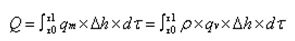
Q: the amount of heat released or absorbed by the system, J or kWh;
Qm: the mass of water flowing through the heat meter, kg/h;
Qv; the volume flow of water flowing through the heat meter, m3 / h;
P: the density of water flowing through the heat meter, kg / m3;
△h: the enthalpy difference of water at the inlet and outlet temperatures of the heat exchange system, J/kg;
t: time, h;
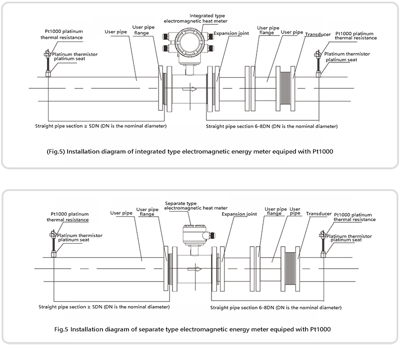
Ⅲ.Product Classification
1.Integrated type electromagnetic heat meter 2. Separate type electromagnetic heat meter

Ⅳ.Instrument Selection
(1) Selection code
| Mode | ||||||||||
| LDR- | □ | □ | □ | □ | □ | □ | □ | □ | □ | Description |
| Nominal diameter | 10·600mm | |||||||||
| Assembly | S | Integrated type | ||||||||
| L | Electrode material | |||||||||
| Electrode material | M | Stainless steel | ||||||||
| Output mode | 0 | No output | ||||||||
| 1 | 4-20mA/1-5KHz | |||||||||
| 2 | 4-20mA | |||||||||
|
Lining material |
X | Rubber | ||||||||
| F | PTFE | |||||||||
| J | Polyurethane rubber | |||||||||
|
Local display |
0 | Without local display | ||||||||
| 1 | Local display | |||||||||
|
Communication mode |
0 | No communication | ||||||||
| 1 | RS485 | |||||||||
| 2 | RS232 | |||||||||
| 3 | Modbus | |||||||||
| 4 | Hart | |||||||||
| Grounding ring | 0 | Without grounding ring | ||||||||
| 1 | With ground ring | |||||||||
| 2 | With Grounded electrode | |||||||||
| Upper limit flow | (n) | Upper limit flow (range)m3/h | ||||||||
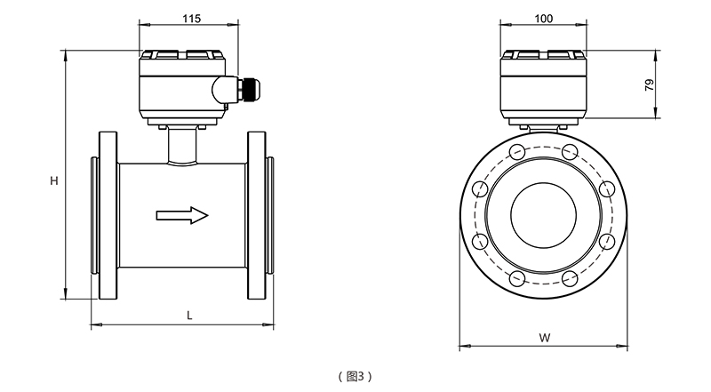
1.Integrated type dimensional drawing: (Fig. 2) (Table 2)

Integrated type dimensions is shown: (Table 2)
| Caliber (mm) | Dimensions | Weight(kg) | ||
| L | W | H | ||
| 10 | 200 | 90 | 290 | 6 |
| 15 | 200 | 9S | 315 | 6 |
| 20 | 200 | 105 | 315 | 6.5 |
| 25 | 200 | 115 | 345 | 6.8 |
| 32 | 200 | 150 | 315 | 7.1 |
| 40 | 200 | 150 | 315 | 7.6 |
| 50 | 200 | 165 | 320 | 9.9 |
| 65 | 200 | 185 | 350 | 10.6 |
| 80 | 200 | 200 | 365 | 12.3 |
| 100 | 250 | 220 | 380 | 14.7 |
| 125 | 250 | 250 | 410 | 17.9 |
| 150 | 300 | 285 | 440 | 24.6 |
| 200 | 353 | 404 | 495 | 2.7 |
| 250 | 450 | 395 | 560 | 43.5 |
| 300 | 500 | 445 | 600 | 58 |
| 350 | 550 | 505 | 670 | 78 |
| 400 | 600 | 565 | 720 | 97 |
| 450 | 450 | 615 | 765 | 110 |
| 500 | 500 | 670 | 820 | 22 |
| 600 | 600 | 780 | 930 | 161 |
| 700 | 700 | 860 | 1010 | 241 |
| 800 | 800 | 975 | 1110 | 420 |
Separate type dimensions is shown: (Table 4)
| Caliber(mm) | Dimensions | Weight(kg) | ||
| L | W | H | ||
| 10 | 200 | 90 | 195 | 5.5 |
| 15 | 200 | 95 | 220 | 5.5 |
| 20 | 200 | 105 | 220 | 6 |
| 25 | 200 | 115 | 220 | 6.3 |
| 32 | 200 | 150 | 220 | 6.6 |
| 40 | 200 | 150 | 220 | 7.1 |
| 50 | 200 | 165 | 225 | 9.4 |
| 65 | 200 | 185 | 255 | 10.1 |
| 80 | 200 | 200 | 275 | 11.8 |
| 100 | 250 | 220 | 285 | 14.2 |
| 125 | 250 | 250 | 315 | 17.4 |
| 150 | 300 | 285 | 346 | 24.1 |
| 200 | 353 | 404 | 400 | 32.2 |
| 250 | 450 | 395 | 465 | 43 |
| 300 | 500 | 445 | 505 | 58 |
| 350 | 550 | 505 | 575 | 78 |
| 400 | 600 | 565 | 625 | 97 |
| 450 | 450 | 615 | 670 | 112 |
| 500 | 500 | 670 | 725 | 122 |
| 600 | 600 | 780 | 835 | 161 |
| 700 | 700 | 860 | 915 | 241 |
| 800 | 800 | 975 | 1015 | 420 |
1. The pipe must be cleaned before the heat meter installation;
2. The heat meter is a precision meter, it must be careful when installing, and it is forbidden to lift the meter head and sensor wire; it is forbidden to squeeze the temperature sensor to prevent damage to the meter;
3. The direction indicated by the arrow of the heat meter sensor body indicates the direction of water flow, and theoretically, it is not allowed to reverse;
4. The front end of the heat meter pipe must be equipped with a filter of the corresponding diameter;
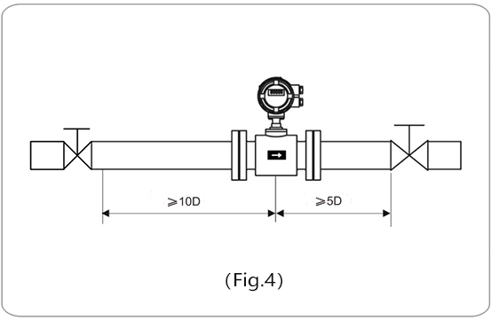
5. When installing the heat meter flow sensor, it shall ensure that there is at least 10 pipe diameter straight pipe sections upstream of the heat flow direction of the heat meter pipe, and at least 5 pipe diameter straight pipe sections downstream of the heat meter pipe;
6. The two ends of the heat meter must be equipped with the corresponding diameter valve, which can be separated from the heat meter for the cleaning and maintenance of the heat meter during use;
7.Installation diagram: Figure (5), Figure (6)


 South China