 Chinese
 English
 Current position:
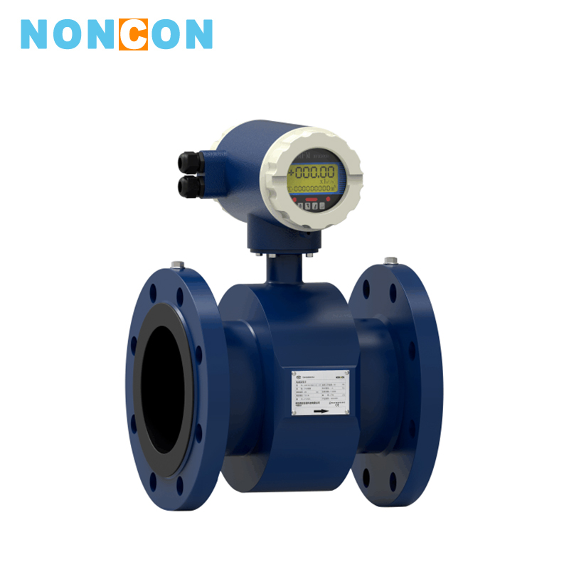


<
>
LDB Intelligent Type Electromagnetic Flowmeter
application:
medium:
Measuring acid and alkali, liquid alkali, mine water, hot water, sewage.
The LDB intelligent type electromagnetic flowmeter consists of a sensor and a converter. It is based on Faraday's law of electromagnetic induction, which is used to measure the volume flow of conductive liquid with conductivity greater than 5μs/cm. It is an inductive meter for measuring the volume flow of conductive medium. In addition to measuring the volume flow of general conductive liquid, it can also be used to measure the volume flow of strong corrosive liquids such as strong acid and alkali and uniform liquid-solid two-phase suspension liquid such as slurry, pulp and paper pulp. It is wdely used for flow measurement of petroleum, chemical, metallurgy, textile, papermaking, environmental protection, food and other industrial sectors and municipal management, water conservancy construction, rivers and other fields.
Detailed introduction
I.Features■ Full digital processing, strong anti-interference ability, reliable measurement, high precision, flow measurement range can reach 150:1;
■ Ultra-low EMI switching power supply, large voltage range of suitable power supply, good anti-EMI performance;
■Use 16-bit embedded microprocessor, with fast operation speed, high precision, and programmable low-frequency rectangular wave excitation,improving the stability of flow measurement and low power consumption;
■Use SMD parts and surface mount (SMT) technology, high circuit reliability;
■ No moving parts in the pipe, no flow blocking parts, and there is almost no additional pressure loss in the measurement;
■ It can modify the range online on site according to the actual needs of users;
■The measurement results are independent of the physical parameters such as flow velocity distribution, fluid pressure, temperature, density, viscosity;
■High-definition backlit LCD display, full Chinese menu operation, easy to use, easy to operate, easy to learn and understand;
■With digital communication signal output such as RS485, RS232, Hart and Modbus (optional);
■With self-test and self-diagnosis function;
■ With hourly total recording function, recording the total amount of flow in hours, suitable for time-sharing measurement (optional);
■ There are three Integrators, which can display the forward accumulation amount ,the reverse accumulation amount and the difference calculation amount respectively.. There is an internal power-down clock, which can record 16 power-down times. (optional);
■ With infrared handheld operator, 115KHZ communication rate, it can operate all functions of converter remotely without contact (optional).
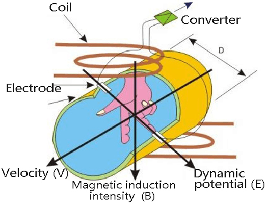
Ⅱ.Working Principle
According to the principle of Faraday electromagnetic induction, a pair of detecting electrodes are mounted on the wall of the pipe perpendicular to the axis of the measuring pipe and the magnetic line of force. When the conductive liquid moves along the axis of the measuring pipe, the conductive liquid cuts the magnetic line of force to generate an induced potential.The induced potential is detected by the two detection electrodes and the value is proportional to the flow rate. The value is: E=KBVD
Where: E- induced potential;
K-the factor related to the magnetic field distribution and the axial length;
B-magnetic induction intensity;
V-conductive liquid average flow rate;
D-electrode spacing; (measure inner diameter of the pipe)
The sensor transmits the induced potential E as a flow signal to the converter. After a series of digital processing such as amplification and conversion filtering, the instantaneous flow rate and the accumulated flow rate are displayed by the dot matrix liquid crystal with backlight. The converter has 4-20mA output, alarm output and frequency output, and has RS-485 communication interface, and supports HART and MODBUS protocols.
Ⅲ.Composition and Structure
The electromagnetic flowmeter consists of the following components:

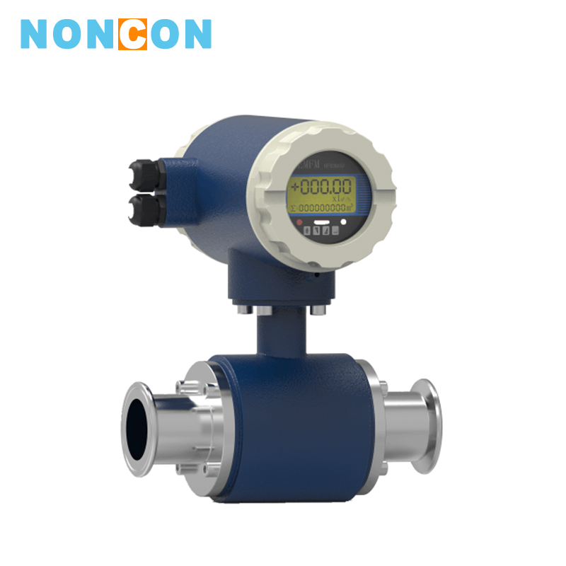
The electromagnetic flowmeter mainly consists of a sensor and a converter. The sensor includes a flange, a lining, an electrode, a measuring pipe, an excitation coil, a sensor housing and so on; the converter includes an internal circuit board and a converter housing.
1.Converter: provides a stable excitation current for the sensor, at the same time, converts the induced electromotive force obtained by the sensor into a standard electrical signal, and displays real-time flow and parameters for display, control and adjustment of the flow.
2.Lining: a complete layer of electrically insulating corrosion-resistant material on the inside of the measuring pipe and on the flange sealing surface.
3.Electrode: a pair of electrodes mounted on the wall of the measuring pipe to detect the flow signal, and another 1-2 grounding electrodes mounted for the grounding and anti-interference of the flow signal measurement.
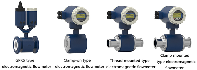
Ⅳ.Instrument Classification
1.According to the instrument structure, the vortex flowmeter can be divided into three categories, namely:
■ Full pipe type electromagnetic flow meter
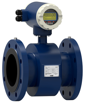
① No resistance parts in the measuring pipe, no pressure loss.
② With simple structure, the electromagnetic flowmeter measuring pipe can use different lining according to different qualifications, and the reliability is high.
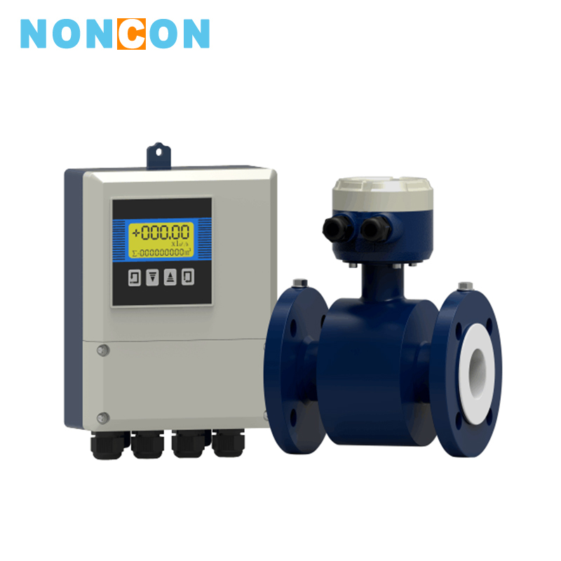
■Separate type electromagnetic flowmeter

The converter and the main body are installed separately, which is convenient for centralized installation and easy to read data.
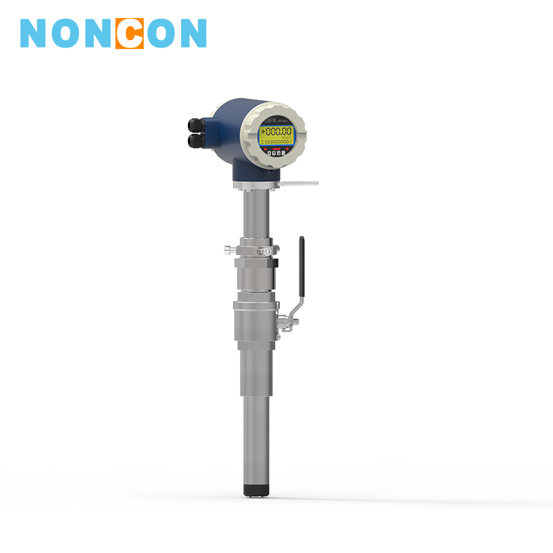
■Plug-in type electromagnetic flowmeter
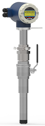
It is widely applicable to the flow measurement of large caliber conductive liquid medium in various industries.
①Wide nominal diameter range, suitable for all caliber pipes between DN150~DN3000.
②The sensor uses novel excitation mode, low power consumption, stable zero point and high precision. The flow range can reach 1500:1.
Ⅴ.Meter Selection
(1)Product selection
| Model | Description | |||||||||
| LDB- | □ | □ | □ | □ | □ | □ | □ | □ | □ | Full pipe type electromagnetic flowmeter |
| LDC- | Plug-in type electromagnetic flowmeter | |||||||||
| Nominal diameter | 10-2200mm | |||||||||
| Assembly | S | Integrated type | ||||||||
| L | Separate type | |||||||||
| Electrode material | M | Stainless steel | ||||||||
| T | Ti (titanium) | |||||||||
| D | Ta(tantalum) | |||||||||
| H | Hastelloy | |||||||||
| P | Pt platinum | |||||||||
| N | Ni nickel | |||||||||
| Output mode | 0 | No output | ||||||||
| 1 | 4-20mA/1-5KHz | |||||||||
| 2 | 4-20mA | |||||||||
| Lining material | X | Rubber | ||||||||
| F | PTFE | |||||||||
| P | Polyethylene | |||||||||
| J | Polyurethane rubber | |||||||||
| Local display | 0 | No local display | ||||||||
| 1 | Local display | |||||||||
| Communication mode | 0 | No communication | ||||||||
| 1 | RS485 communication (MODBUS protocol) | |||||||||
| 2 | HART communication | |||||||||
| 3 | GPRS wireless communication | |||||||||
| Grounding ring | 0 | Without grounding ring | ||||||||
| 1 | With grounding ring | |||||||||
| 2 | Ground electrode | |||||||||
| Upper limit flow | (n) | Upper limit flow (range) m3/h | ||||||||
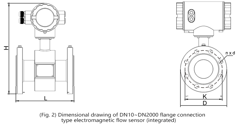
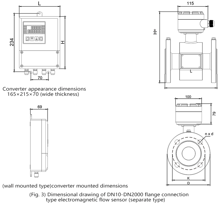
Ⅵ.Installation Dimension
Ⅶ.Electromagnetic Flowmeter Installation Precautions
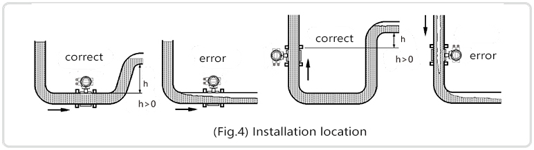
1. Installation location
The pipe must be completely filled with liquid, which is critical, otherwise the flow display will be affected and measurement errors will occur. The pipe structure must be designed to ensure that the flow pipe is always filled with fluid.When the fluid is diverted or combined with solid particulate deposits,vertical installation is recommended, but for vertical installations,it need to follow the fluid direction from bottom to top to ensure that the pipe is full of fluid.
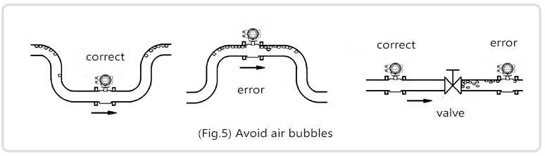
Avoid air bubbles. If air bubbles enter the flow pipe, the flow display will be affected ,and measurement errors will occur. When the fluid contains air bubbles, the pipe must be designed to prevent air bubbles from accumulating in the flow pipe. If there is a valve near the flow measuring pipe, place the pipe upstream of the valve as much as possible to avoid pressure reduction and bubble generation.
2. Installation direction
If the electrode is perpendicular to the ground, bubbles gathered at the top or deposits deposited at the bottom can cause measurement errors. Install the separate type flow pipe junction box and the integrated type converter on top of the pipe system to prevent water from entering.
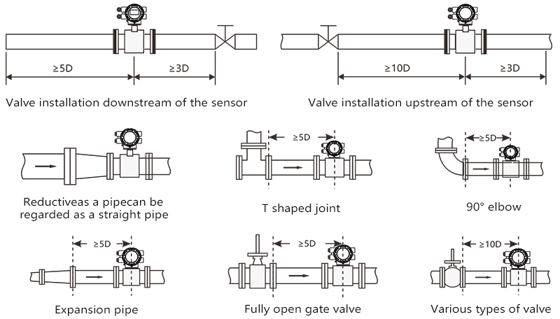
3. Straight pipe Sections Requirements and Environmental Requirements
Do not install anything near the flow pipe that may interfere with the magnetic field, the induced signal voltage, and the flow field distribution of flow pipe. In general,it is necessary to ensure a 5D of straight pipe section for the upstream and a 3D of straight pipe section for the downstream. If there are interference flow parts such as elbows and valves, the length of the straight pipe section required should be larger. It is highly recommended to install the valve at the downstream end to avoid flow fluctuations in the flow pipe and to avoid counting from the empty pipe status.
4. Maintain stable fluid conductivity
Avoid installing the flowmeter in the position of uneven fluid conductivity. If chemicals are injected near the upstream end of the electromagnetic flowmeter, it may affect the flow display. To avoid this, it is recommended to inject chemicals to the downstream end of the flowmeter. If it must be injected from the upstream end, use a long enough straight pipe (approximately 5D) to ensure that the fluid is well mixed with the chemicals.


 South China