 Chinese
 English
 Current position:
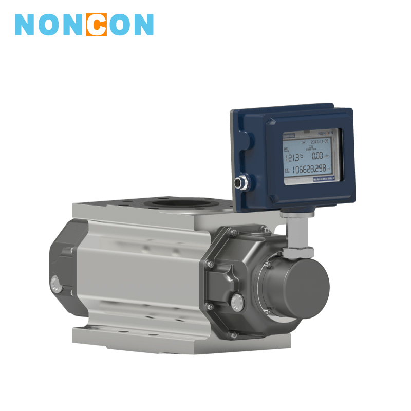

<
>
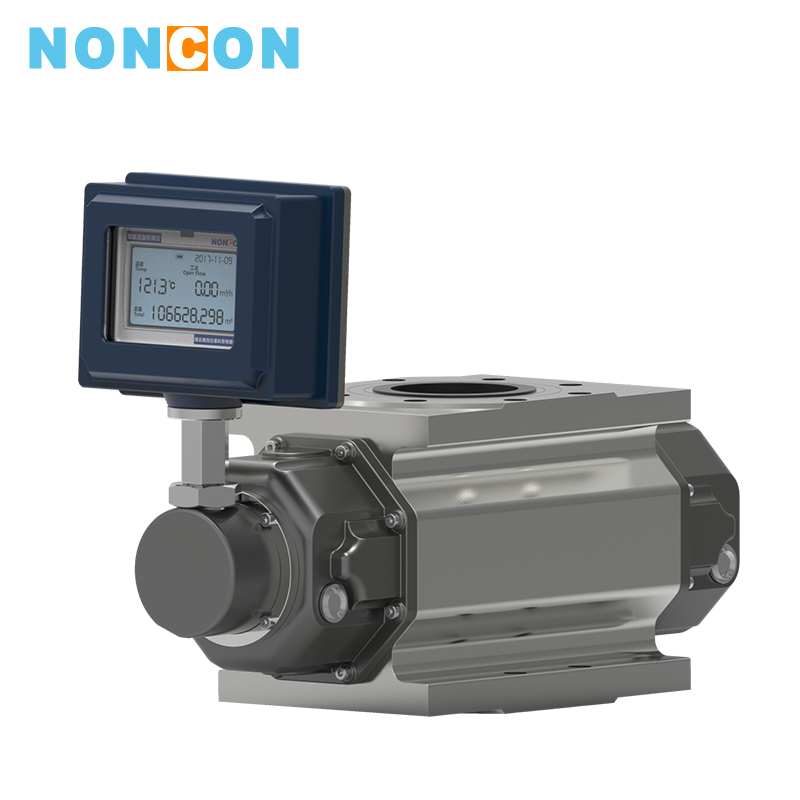
LLGQ Gas Roots (Roots) Flowmeter
application:Petroleum, chemical, electric power, metallurgy, urban gas supply, etc.
medium:
For gas flow such as natural gas.
The gas roots flowmeter has been used as a volumetric meter for more than 100 years. With the features such as high precision, wide range, small volume, light weight, convenient installation and maintenance, reliable and durable service life, it is widely used in natural gas, coal gas, air and other gas flowmeters.It is an ideal flowmeter device for urban gas, oilfield chemical, scientific research and other departments at home and abroad.
Detailed introduction
Ⅰ.Features■ It integrates high-precision temperature, pressure, flow sensor and intelligent volume corrector to detect the temperature, pressure and flow of the measured gas and perform automatic flow track and compensation and compression factor correction.
■Use advanced microcomputer technology and high-performance integrated chip, it has powerful functions and superior performance.
■The circuit uses the surface mount technology, with compact structure, strong anti-interference ability and high reliability.
■Use advanced micro-power high-tech, the whole machine has low power consumption, that is, it can run with built-in battery for long time, and can be operated by external power supply.
■ According to the flow frequency signal, the meter factor can be automatically corrected linearly in five segments, to improve the accuracy of the meter.
■ With fault self-diagnosis and alarm function, high reliability, LCD display, clear and intuitive, easy to read.
■The flowmeter has a pulse signal output, and can also output 4~20mA standard analog signal according to user needs.
■ The meter has its own real-time database, and it forms a meter reading network through R5-485 communication interface to facilitate centralized data collection and real-time management.
■Use advanced micro-power technology, low power consumption. It can run for more than five years using built-in battery. It displays the flow value locally with various signal output functions to meet the needs of different fields and systems. It uses EEPROM data storage to save user parameters, manufacturer parameters and a certain history.
■ Use high-contrast three-line LCD display for displaying date, standard cumulative flow, standard instantaneous flow, medium temperature, pressure, and battery voltage.
■ With real-time data storage function, it can avoid data loss when battery is replaced or suddenly power down. In the power-off state, internal parameters can be permanently saved.
Ⅱ.Structure and Working Principle
(1). The flowmeter consists of 5 parts (see Figure 1)
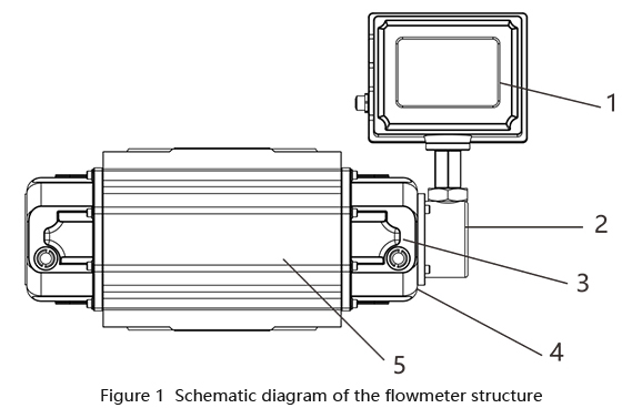
1. Intelligent flow totalizer 2.Flow sensors 3.Pressure sensor
4. Temperature sensor 5.Gas roots flowmeter (mechanical)
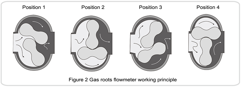
(2)Intelligent gas roots flowmeter working principle (see Figure 2)
The intelligent gas roots flowmeter consists of a housing, a conjugate rotor and an intelligent flow totalizer. Under the action of the pressure difference between the inlet and outlet of the circulating gas (P inlet>P>outlet),the pair of conjugate maintain the correct relative position of the rotor through the precision-machined adjusting gear.The optimum working gap between the rotor, the rotor and the housing, and the rotor and the wall plate achieves a continuous non-contact seal. For each revolution of the rotor,it outputs four times the effective volume of the metering chamber, and the number of revolutions of the rotor is transmitted to the intelligent flow totalizer through the magnetic sealing coupling device and the speed reducing mechanism, to display the cumulative volume of the output gas.
(The figure shows only a quarter cycle).
3.Intelligent flow totalizer working principle
The intelligent flow totalizer consists of temperature and pressure detection analog channel, flow sensor channel and microprocessor unit, and is equipped with an external signal interface to output various signals. The microprocessor in the intelligent flow totalizer performs temperature and pressure compensation and compression factor correction according to the gas equation. The gas equation is as follows:
Where:
Qn: volume flow rate under standard condition (m3/h);
Qg: volume flow rate under working condition (m3/h);
Pg: meter pressure at the flowmeter pressure detection point (KPa)
Pa: local atmospheric pressure (KPa);
Tg: absolute temperature(273.15 + t) (K) of the medium;
t: measured medium temperature (°C);
Zn: compression factor under standard condition;
Zg: compression factor under working condition;
Tn: absolute temperature (273.15+20) (K) under standard state;
Pn: standard atmospheric pressure (101.325KPa);
P: P = Pa + Pg.
Note: for natural gas Zn/Zg=Fz2 and Fz is called the ultra-compressed factor, this product is calculated according to the formula in SY/T6143-1996 standard of China national petroleum corporation.
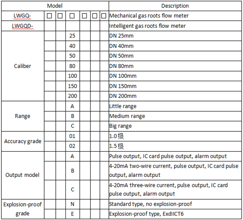
Ⅲ.Flowmeter Selection
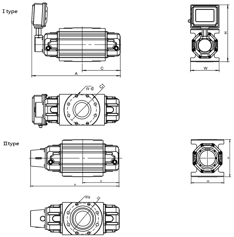
Ⅳ.Flowmeter Outline Dimension
The flowmeter installation dimensions are shown in Figure 3. The flange is in accordance with GB/T9119-2000.
Ⅴ.Flowmeter installation precautions and requirements
■ Before selecting the flowmeter, the appropriate model and specifications shall be selected according to the pressure, flow, temperature and process requirements of the metered gas. (see “Flow Conversion”for the calculation method, ).
■ Before installing the flowmeter, the inlet and outlet packages shall be removed. It is necessary to prevent the particulate impurities from entering the measuring chamber. For example, the surface of the measuring chamber is coated with anti-rust oil, which can be cleaned with gasoline or kerosene, and the impurities in the pipe are strictly removed. A filter shall be installed upstream of the flowmeter to prevent rust, welding slag and other impurities from entering the metering chamber.
■When the flowmeter is installed, the rotor axis shall be kept as level as possible regardless of whether the inlet and outlet are vertical or horizontal.
■ When the gas pressure fluctuation range is large, in order to ensure the measurement accuracy, a regulator shall be installed upstream of the flowmeter.
■ In order to prevent rust, welding slag and other impurities in the newly installed pipe from entering the flowmeter, users shall first install the transition pipe on the installation position of the flowmeter.After venting for a period of time, make sure that there are no large particles of impurities, then install the flowmeter. When installing the flowmeter, make sure that the flowmeter center is aligned with the pipe center, no misalignment, and the flowmeter is not affected by external forces (including axial and tangential directions ).
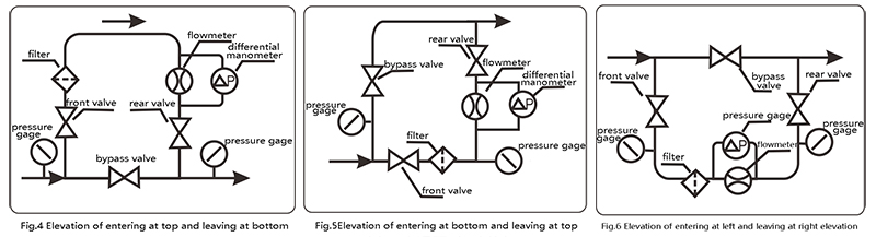
■ When installing the flowmeter vertically. It is recommended that the flow direction of the gas is entering at top and leaving at bottom. In special cases, it can perform entering at bottom and leaving at top,entering at left and leaving at right.However, special descriptions are required when ordering. The standard product of the flowmeter is entering at top and leaving at bottom. The front and rear valves and bypass pipes should be installed when installing the flowmeter to ensure that there is no need to stop the air during maintenance. Figure 4, Figure 5, and Figure 6 show the typical system diagrams for entering at top and leaving at bottom,entering at bottom and leaving at top,entering at left and leaving at right.entering at left and leaving at right.Tpical system diagrams for three flowmeter pipe installation for reference.
■ The pipes and fittings of each part of the flowmeter installation must be properly sized, and the flowmeter body must not be subjected to abnormal external forces.
■ After the flowmeter is installed, inject the lubricating oil (GB486~65 high-speed oil H5) from the oil filling port to the oil window center line (note that you cannot add more).
■ Perform regular or irregular inspection during use to ensure sufficient and clean lubricant.If the lubricant is black or the oil level is higher than the center line of the oil window, it indicates the lubricant is deteriorated or has impurities.In this case, replace the lubricant. If the oil level is 3mm below the center line of the oil window, it indicates the loss of lubricating oil and needs to be added to the center line of the oil window. When filling the lubricating oil, it must close the front and rear valves of the flowmeter, and after the gas is drained, then the lubricating oil is added.
■When the flowmeter is in operation, all valves shall be opened and closed slowly to prevent the strong impact of the airflow and damage the flowmeter.
■After the flowmeter is in operation for a period of time, if the pressure drop of the filter is increased, the filter shall be cleaned or the filter medium shall be replaced. If the pressure drop of the flowmeter is increased, and the starting flow rate is increased, and it can flush the metering chamber with clean gasoline or kerosene.
■ When the flowmeter is deactivated for a long time, it should empty the lubricating oil , and the metering chamber shall be flushed with gasoline, then the inlet and outlet shall be sealed and placed in a dry place.
■ When the flowmeter is used to measure city gas (natural gas, artificial gas, etc.), its impurity content shall meet the content standard of China's “Urban Gas Design Code”(GB50028-93).


 South China