Principle of heat meter
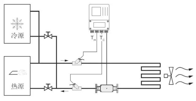
The working principle of the heat meter by heat supply of hot water (cold water) to high (low) temperature into the heat exchange system (radiator, heat exchanger or complex system composed of them), with low (high) temperature of the outflow, in this process, the release or absorption of heat to the user through the heat exchange (Note: this process involves energy exchange between the heating system and cooling system). When the water flow through the heat exchange system, according to the temperature sensor are given flow sensor flow and matching of supply and return water temperature, and water flow through time, through the calculator and display the system to release or absorb heat. Q= formula QM * 1 h * 0 delta tau tau tau Rho formula d = * QV * * D H delta tau tau tau 0 1
Q: the amount of heat released or absorbed by a system, J or kWh;
QM: the mass flow of water through the heat meter, kg/h;
QV: volume flow of water through a heat meter, m3/h;
P: the density of the water flowing through the heat meter, kg/m3;
H: enthalpy difference at inlet and outlet temperature of heat exchange system, J/kg;
T: time, H.
Measuring principle of electromagnetic flowmeter
The principle of electromagnetic flowmeter is based on Faraday's law of electromagnetic induction. Two electromagnetic coils in Figure 3 the upper and lower ends produce constant or alternating magnetic field, when the conductive medium flows through the electromagnetic flowmeter, flow meter on the tube wall around between the two electrodes can detect the induced electromotive force, the induced electromotive force and the size of the conductive medium velocity, magnetic induction intensity, conductor width (measuring tube flowmeter is proportional to the diameter) can be calculated through the medium flow. The induction electromotive force equation is:
E=K x B * V * D
Where: e - induced electromotive force;
K instrument constant;
B magnetic induction;
The V section average flow velocity in pipe measurement;
The inner diameter of the measuring tube.
Measurement of flow, fluid flowing through the flow direction perpendicular to the magnetic field, which induces a flow is proportional to the average velocity of the induced potential of conductive fluid, so the conductivity measured liquid is higher than the minimum conductivity of ---5us/cm (theory of electromagnetic flowmeter can measure the conductivity of more than 5 mu s/cm conductive medium, but should ensure that the use of electromagnetic flowmeter in the measured conductivity at 50 s/cm and above the actual measurement (larger than the theoretical value of one to two orders of magnitude) in the environment, and must be in the conductivity online measurement values for the base date). The induction voltage signal detected by the two electrode, and cable connected to the converter, through a series of analog and digital signal processing after the cumulative flow and transient flow in the converter on the screen display.
Electromagnetic flowmeter structure
From the following figure, electromagnetic flowmeter mainly has the following components:
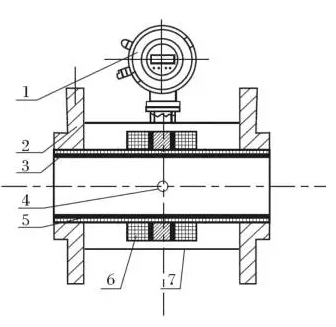
1- converter; 2- flange; 3- insulation lining;
4- electrodes; 5- measuring tubes; 6- excitation coils;
7- shell
The electromagnetic flowmeter is mainly composed of two parts which include sensors and switches, sensors, motor flange, lining, measuring tube, excitation coil, and other parts of the sensor housing; converter includes a circuit board inside the converter housing and etc..
(1): converter provides excitation current stability of the sensor, the induced electromotive force through the sensor amplifier, converted into electrical signals or standard frequency signal, and display the real-time flow and parameters, display, control and regulation for traffic.
(2) flange: used to connect with process piping.
(3) lining: a complete layer of electrical insulation and corrosion resistant material on the inside of the measuring tube and the sealing surface of the flange.
(4) electrode: a pair of electrodes is arranged on the wall of the measuring tube perpendicular to the magnetic line of force to detect the flow signal, and the electrode material can be selected according to the corrosion performance of the tested medium. Another 1-2 earth electrodes are used for grounding and anti-interference of flow signal measurement.
(5) measuring tube: flow through the measured medium in the measuring tube. The measuring tube is welded by stainless steel and flanges without magnetism and is lined with insulating lining.
(6) excitation coil: a coil of coils is arranged on the upper and lower sides of the measuring tube to produce a working magnetic field.
(7) shell: not only plays a protective role, but also acts as a sealing device.
 Chinese
 English

 Current position:


 South China